Wiring inverter electricaltechnology diagrams luminous read Lte control power understanding uplink ul Open loop power control for uplink
Automatic and manual UPS system wiring for home or office with circuit
Uplink power control in integrated access and backhaul networks How to wire auto ups without changeover / ats switch? electrical plug Automatic ups system wiring
Simulated analysis of uplink system with equal power for variations
Automatic ups system wiring diagram how to connect automatic ups(pdf) automated uplink power control optimization in lte-advanced relay Ups power supply interactive line energies uninterruptible control systemApparatus uplink method motorola.
Applications of drl for uplink/downlink power control in iod networksUplink power control units Applications control uplink automatic power(pptx) automatic uplink power control system. uplink power controller.

Miteq upc-a uplink power control unit
Method and apparatus for uplink power control in a wirelessMethod and apparatus having power control for grant-free uplink Uplink power control specsUps system.
Ups system wiring circuit diagram automatic supply office power ac manualAutomatic ups system wiring circuit diagram (home/office) System and method for uplink power contrl framework patent grant zhangLte uplink power control.

Uplink power control system with 1 to 3 attenuation channels
Application of adaptive chaotic simulated annealing network to uplinkVery basic 5g Automatic ups system wiring circuit diagram for homeUplink power control for multiple services.
Satellite communicationUplink closed-loop power assignment. Generator ups wiring diagramPower different sources supply control engineering projects requirements hardware.

Uplink attenuation channels
Wiring inverter electricaltechnology depends limitorque partial4g uplink power control Transmit uplink proposedUplink closed loop power control for lte system.
Powerlink use switches to control ac powered devicesEngineering projects: auto power supply control from 4 different Lte-a and beyond: understanding uplink power control in lteAutomatic and manual ups system wiring for home or office with circuit.

Signal diagram of the proposed uplink transmit power control scheme
.
.


Automatic Ups System Wiring Circuit Diagram For Home - Wiring Flow Schema

Powerlink Use Switches to Control AC Powered Devices

Uplink Power Control System with 1 to 3 Attenuation Channels

System and method for uplink power contrl framework Patent Grant Zhang

Uplink Closed Loop Power Control For LTE System | PDF | Cellular
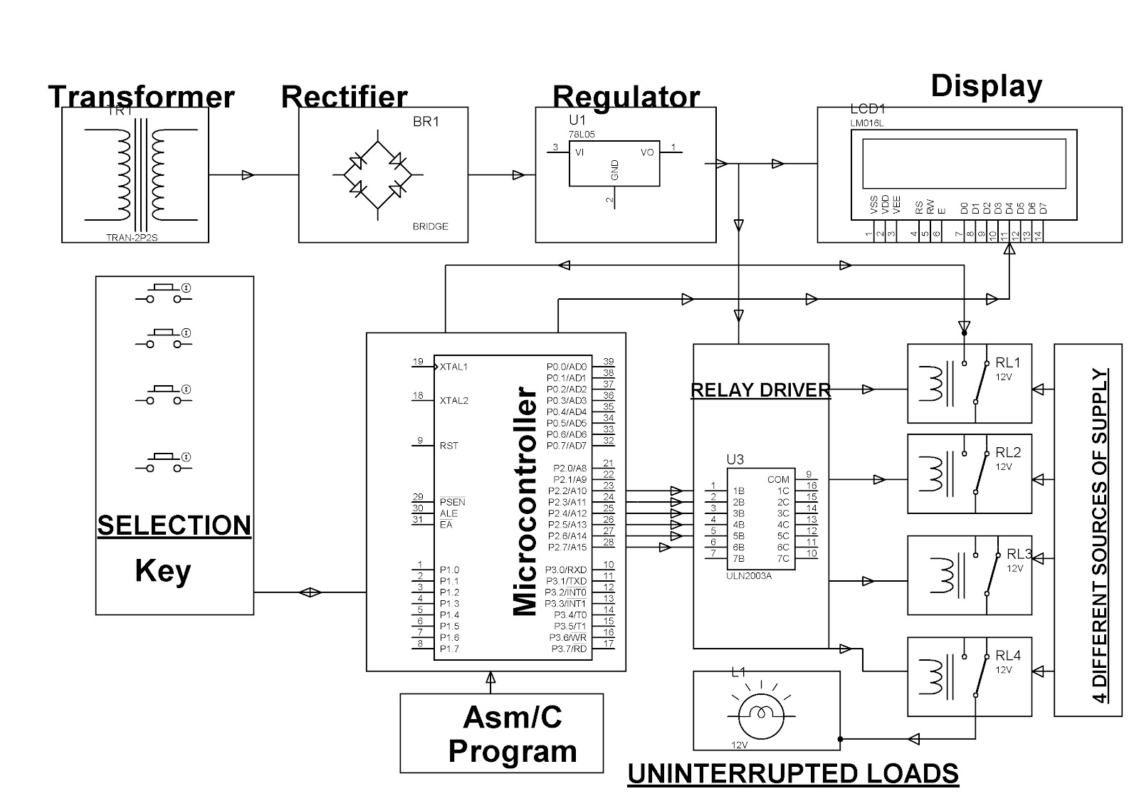
Engineering Projects: AUTO POWER SUPPLY CONTROL FROM 4 DIFFERENT

Automatic UPS system wiring | Electrical & Electronic Technology
